Ripple mapping is a novel, three-dimensional, electroanatomic mapping tool that displays each electrogram at its corresponding 3-dimensional coordinate as a dynamic moving bar, which changes in length according to the electrogram voltage-time relationship. We present the case of a 43-year-old male patient with surgically repaired Ebstein's anomaly who previously underwent two unsuccessful ablation procedures for right atrial flutter (cavotricuspid isthmus and intercaval lines). Ripple mapping was decisive, enabling the arrhythmia mechanism to be appropriately recognized, and a distinction to be made between critical areas of the circuit and delayed activated bystander regions.
O mapeamento Ripple é uma nova ferramenta de mapeamento eletroanatómico tridimensional que permite visualizar cada eletrograma na sua coordenada 3D correspondente na forma de uma barra com movimento dinâmico que altera a sua amplitude de acordo com a relação voltagem-tempo do eletrograma. É apresentado um caso de um doente de 43 anos com anomalia de Ebstein corrigida cirurgicamente e previamente submetido a dois procedimentos de ablação por fluter auricular direito (linhas do istmo cavo-tricúspide e intercava) sem sucesso. O mapeamento Ripple foi decisivo, permitiu o reconhecimento apropriado do mecanismo da arritmia e a distinção entre as áreas críticas do circuito e áreas bystander ativadas tardiamente.
Mapping post-surgical and post-ablation complex atrial tachycardia with the routinely used electroanatomical systems is quite challenging. Ripple mapping (RM) is a novel 3D mapping system that displays each electrogram at its corresponding 3D coordinate as a dynamic moving bar that changes in length according to the electrogram voltage-time relationship.1
Case reportWe report the case of a 43-year-old male patient with Ebstein's anomaly (Supplemental Video 1) who previously underwent tricuspid valve repair, right anterior accessory pathway surgical dissection and two unsuccessful ablation procedures for right atrial flutter (cavotricuspid isthmus and intercaval lines). The patient was admitted for recurrent atrial flutter (Supplemental Figure 1) refractory to high-dose amiodarone and a repeat procedure was scheduled.
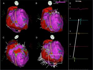
A high density and evenly spread map (2610 points [Supplemental Video 2]) of the severely enlarged right atrium was created using the Pentaray® mapping catheter with a CARTO® 3 v4 CONFIDENSE™ module (Biosense Webster Inc., CA, USA). The color-coded activation map, documenting over 95% of the arrhythmia cycle length, was not interpretable, in particular due to the presence of various “early meets late” areas in distant areas of the atrium. Entrainment mapping was attempted, but a second atrial flutter emerged during pacing maneuvers, rendering the map uninformative. The second atrial flutter was also fully mapped and the color-coded activation map was also unclear. Both maps were then reanalyzed using the RM algorithm. Ripple bars were clipped at 0.25 mV and excluded if less than 0.03 mV in order to remove noise from the signal. A bipolar voltage map was displayed and scar threshold was adjusted to show those areas without Ripple wavefront as scar region. The optimal atrial threshold in this patient was 0.2 mV. Extensive scars related to previous ablation were evident in the cavotricuspid isthmus and throughout the lateral wall, extending from the inferior to the superior vena cava. Visualization of the Ripple bars’ activation direction clarified the mechanism of the first flutter (Figure 1 and Supplemental Video 3): macroreentrant anti-clockwise circuit ascending anteriorly to the crista terminalis, going around the right atrial appendage and descending between the crista terminalis and the intercaval line to the lateral aspect of the scar. RM enables numerous electrograms of interest to be simultaneously displayed in a separate window, with these points marked over the 3D surface as color-coded bars (Ripple marks). This function enabled tracking the propagation of the very low-voltage signals within the scar, throughout the slow conduction isthmus. RM also depicted the second flutter macroreentrant circuit, which was similar to the first but in a clockwise rotation (Figure 2 and Supplemental Video 4). In addition, it revealed a previously unapparent gap at the superior aspect of the intercaval line. Radiofrequency ablation at the critical isthmus terminated the tachycardia. Additional radiofrequency applications were delivered at the intercaval line gap (Supplemental Figure 2). At the end of the procedure, no further arrhythmias were inducible and at 6 months of follow-up, the patient is free of arrhythmic events (Supplemental Figure 3).
Ripple map displayed over a bipolar voltage map depicting the circuit of the initial flutter, showing an activation front ascending anteriorly to the crista terminalis (parallel yellow lines), going around the right atrial appendage and descending between the crista terminalis and the intercaval line (A to D) to a slow conducting isthmus. As the isthmus is a cicatricial zone, the Ripple bars are smaller in number and in amplitude. As such, four Ripple marks and corresponding electrograms are displayed and marked from 1 to 4 (D and E). The slow conduction through the critical isthmus began at mark 1 and spread to mark 4.
Ripple map of the second flutter, displayed over a bipolar voltage map: the wavefront ascended between the crista terminalis and the intercaval line, went around the right atrial appendage and descended anteriorly to the crista terminalis (A to D) through the slow conducting isthmus. As the isthmus is a cicatricial zone, the Ripple bars are smaller in number and in amplitude. As such, six Ripple marks and corresponding electrograms are displayed and marked (D and E). The slow conduction through the critical isthmus began at mark 1 and spread to mark 6.
Mapping complex atrial tachycardia is often challenging due to the limitations of the routinely used electroanatomical systems. Color-coded activation maps are often uninterpretable or even misleading as a result of inappropriate settings for the “window of interest” and incorrect annotation of the low-voltage signals usually present in critical areas, such as the surgical scars, ablation lines and disease-related atrial fibrotic regions. In addition, multiple zones of slow conduction and conduction block can lead to very delayed activation of bystander areas, leading to misinterpretation of the resultant color-coded activation map. Entrainment mapping is also challenging due to the possibility of transformation or termination of the tachycardia.
When superimposed on a surface bipolar voltage map, RM allows the wave propagation to not only be visualized by the relative motion of each ripple bar, but also facilitates understanding the relationship between the arrhythmia's mechanism and the underlying substrate. More importantly, RM does not require a “window of interest” to be set, does not require local activation time annotation, avoids interpolation between points, minimizes the user's post-processing and facilitates the distinction between the arrhythmia's critical circuit and the passive activation of bystander regions.2
In this case of complex atrial tachycardia, RM was decisive, enabling the arrhythmia mechanism to be appropriately recognized, as well as a distinction to be made between critical areas of the circuit and delayed activated bystander regions.
Conflicts of interestThe authors have no conflicts of interest to declare.


